Flip Dot AND Gate
Attempt to make an AND gate using magnetic hematite beads.
Material List:
30 AWG Enameled copper wire
10 mm Hematite magnetic beads
12 mm Dowel or Sharpie marker
Conductive thread
Snap buttons
Metal spring (optional)
Paracord
Painter’s tape
Felt
What is a logic gate?
A logic gate is a device (either virtual or mechanical) used to execute a Boolean function. Logic gates are the bedrock of modern computing.
Logic gates can be divided into two categories:
One input logic gates
Two input logic gates
The One input logic gates are:
Buffer
Inverter

The Two input logic gates are:
AND
NAND
OR
NOR
XOR
XNOR

The AND gate is a basic gate that implements a logical conjunction (^) and it behaves according to the Truth Table above.
An output value of 1 is only possible if both inputs have a value of 1 as well.
Making a mechanical AND Gate:
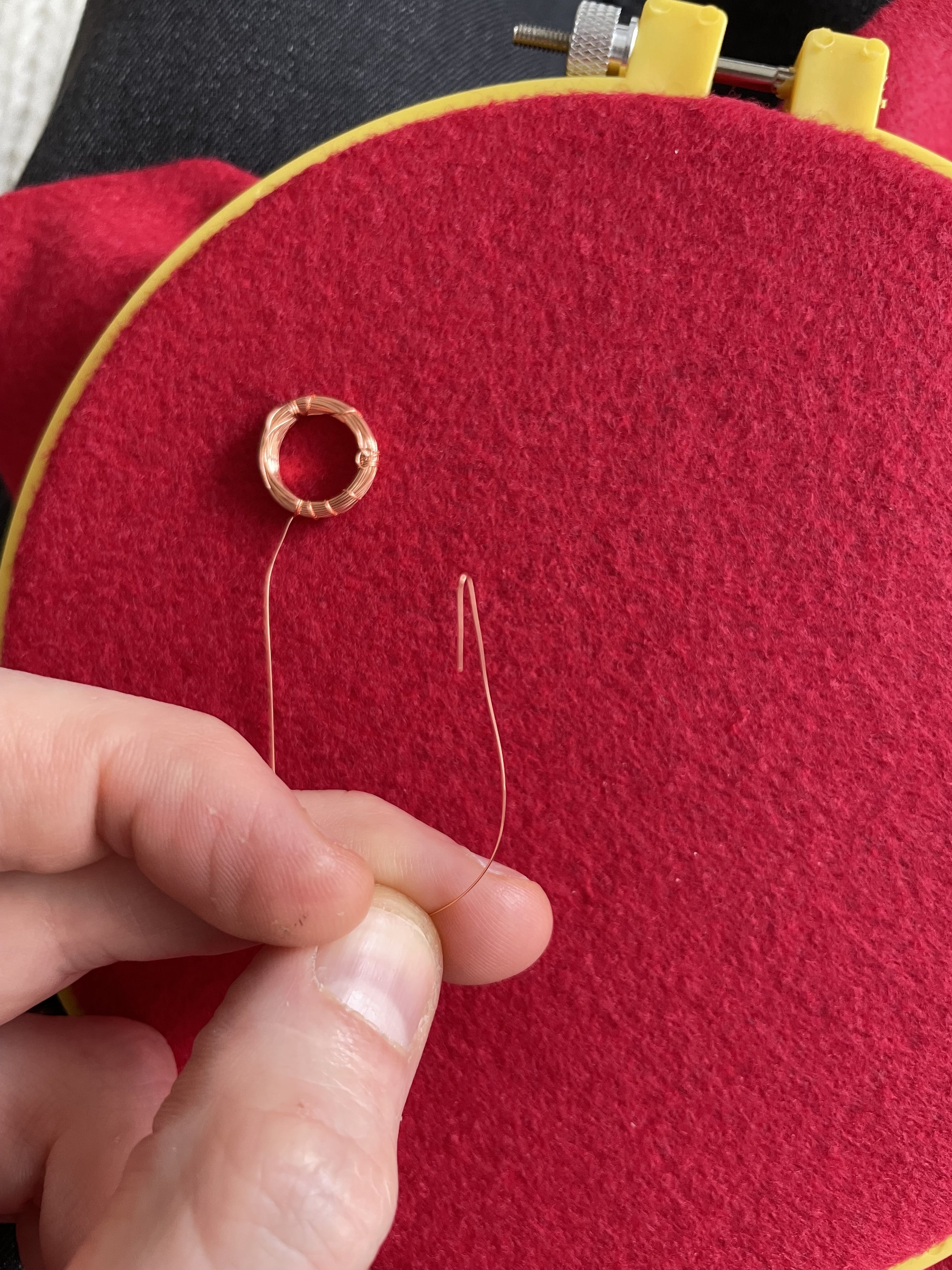
To start, I began by making 3 copper coils using 30 AWG enameled copper wire using a Sharpie marker to help me wound them (more info in the tutorial below).


I subsequently embroidered the coils onto a piece of red felt using conductive steel thread.


Due to issues highlighted in the tutorial (at the end of the page), I had to limit the travel of the flip dots. To do so I cut up the metal spring of a pen. Unfortunately, after this modification was done, I had tremendous difficulties making the dots flip.

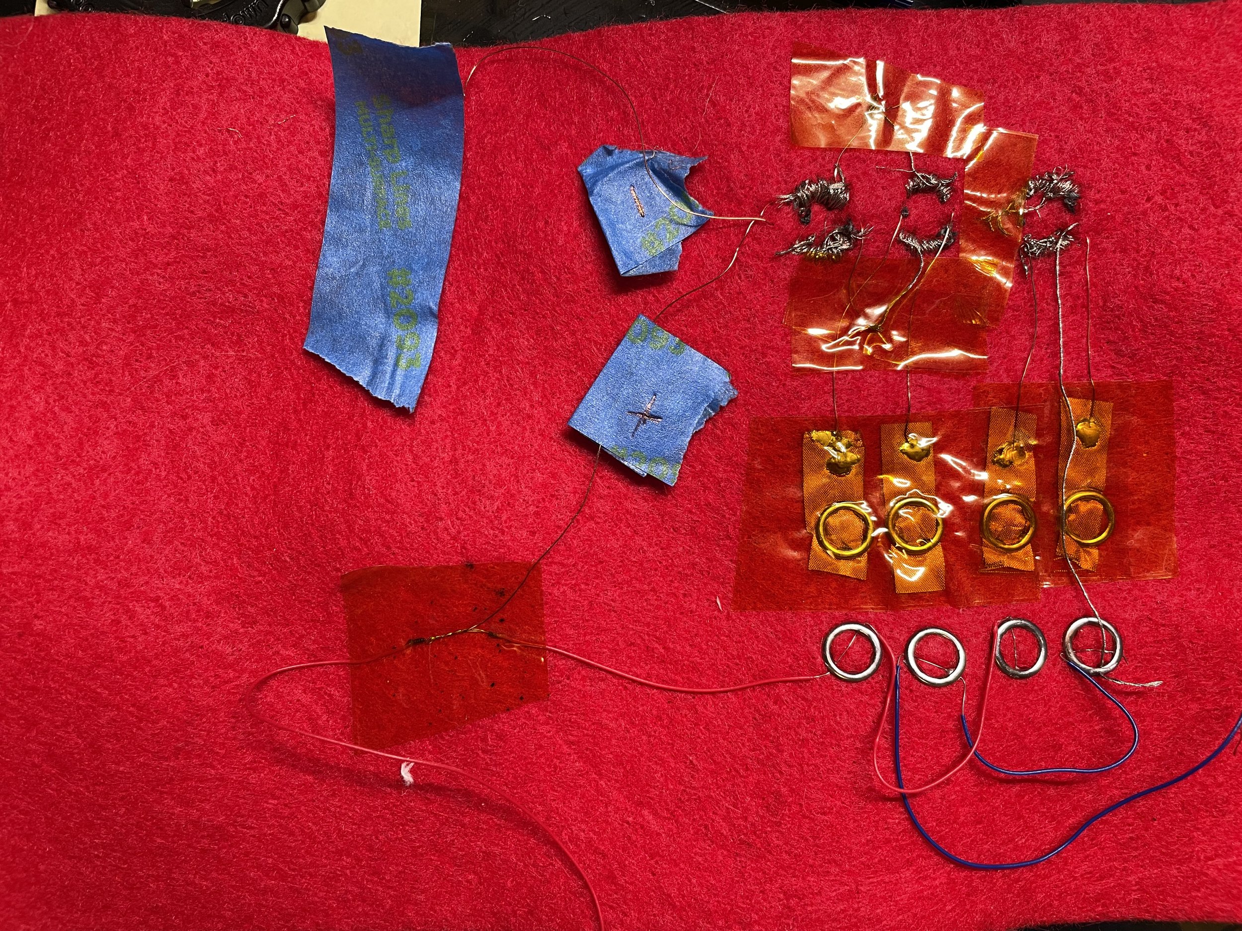
The ugly mess that is the back of my defunct AND gate.

Example of how the AND gate should work: input A (left most bead) is set in the 0 position while input B (center bead) is set in the 1 position. As per the Truth Table above the output remained at 0.
Example of a working AND gate by Irene Posch:


